Sunday, February 28, 2016

Lego Racer

Day 7 (2/16/16)

After we tested our windlasses, we began working with gears and motors. We tested the two different types of lego motors and learned how to use the components to make the motor spin. We learned how to attach the pico cricket, motor board, the motor and the gears the create a gear train that would be powered by the motor.


Day 8 (2/19/16)

Today we started by doing a worksheet to learn more about gears and gear ratios. We analyzed different gear ratios and learned how to put the gears together to make a lego gear train. We learned that going from a small gear to a big one increases the torque by the gear ratio factor. The reverse is true for speed, going from big to small gear increases the speed. These concepts became very important to us as we began designing our lego racer.

Once we finished our worksheet, we began designing our lego racer. We started designing our lego racer by using trial and error. We decided to first make a gear train that would allow the wheels to move and then go from there. Here is what our first design for the car looked like:


To this design, we added a gear train and tested all of our wheels. We ultimately decided to go with the largest wheels and the smallest wheels.

Sara and I then decided to divide and conquer to test out different gear ratios to determine the best configuration. We each worked on our own designs, but shared our findings with each other and incorporated each others ideas.

My first iteration had a gear ratio of 1/8.3. I used a 24 tooth gear connected to the motor that turned a 40 tooth gear below it. The axel with the 40 tooth gear had an 8 tooth gear along the outside. That 8 tooth gear turned a 40 tooth gear that was also on the same axel as another 8 tooth gear. I used a 40 tooth gear intermediately connected with an 8 tooth gear on the axel with the wheels. The design looked like this:


Unfortunately this design was not fast enough because the gear ratio was too high. The gear train provided too much torque to the car and therefore minimized its speed.

While I was working on my design, Sara was also working on testing different gear ratios. She tested gear ratios of 0.6, 0.4, 0.167, and 0.11.

By using the data that Sara got from her designs, we determined that we needed a gear ratio somewhere between 0.12 and 0.4.                                                                                                                                                               
Outside of class we put together more iterations of the lego car that looked like this:


We ended up testing gear ratios of 0.08, 0.04 and 0.24. It turned out that our best lego racer was the one with the 0.08 gear ratio. When we tested the gear ratio of 0.08 we recorded a time of 10.6 seconds.


Day 9 (2/23/16)

Today was race day. Sara and I decided to go with the 0.08 gear ratio car since, when we tested it, it finished with a time of 10.6 seconds. The gear train ended up being set up the same as the first iteration, but instead of a 24 tooth gear on the motor, we attached a 16 tooth gear. We also changed our design slightly to account for the different height of the 16 tooth gear and we added a platform for the weight and for the pico cricket.


When it came time to race the cars, our car did not perform as we intended, nor as we expected. Instead of completing the distance in around 11 seconds, it finished in 20! That was a huge change compared to our test run. Originally we thought our issue might have been due to the batteries, however when we changed the batteries it only improved performance by a few seconds. We think it might have been due to excess friction in the gears, but we are still not quite sure what happened.

If we had more time, we could have refined our design to make the lego structure lighter. Also, we probably would have been able to improve our gear ratio to make the car go even faster. Most of the teams determined that the ideal gear ratio for this scenario was around 1/15. We had a gear ratio of 1/12.5 so we were close, but we could have made our car even faster.


Sunday, February 21, 2016

Well Windlass

Day 4 (2/5/16)

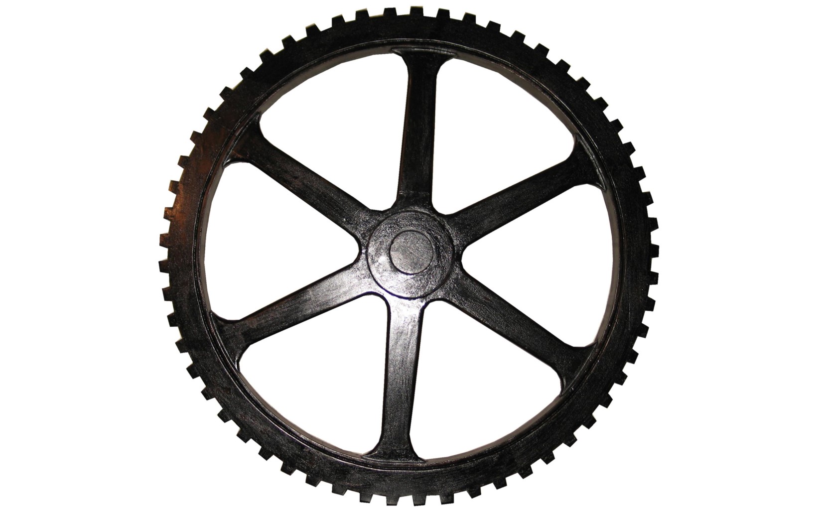
Our second project in Engineering 160 was to design and build a well windlass. A well windlass is "a device that can go over a well and has a hand-powered crankshaft to lift a 'bucket of water' (one liter of water)." Here is an example of a windlass:


We were required to build it completely out of Delrin sheets and rod. We were limited to 500m^2 of 
Delrin sheet and 50cm of Delrin rod, and we were allowed to use any of the fastening techniques that we learned (including the piano wire) to put together the windlass.

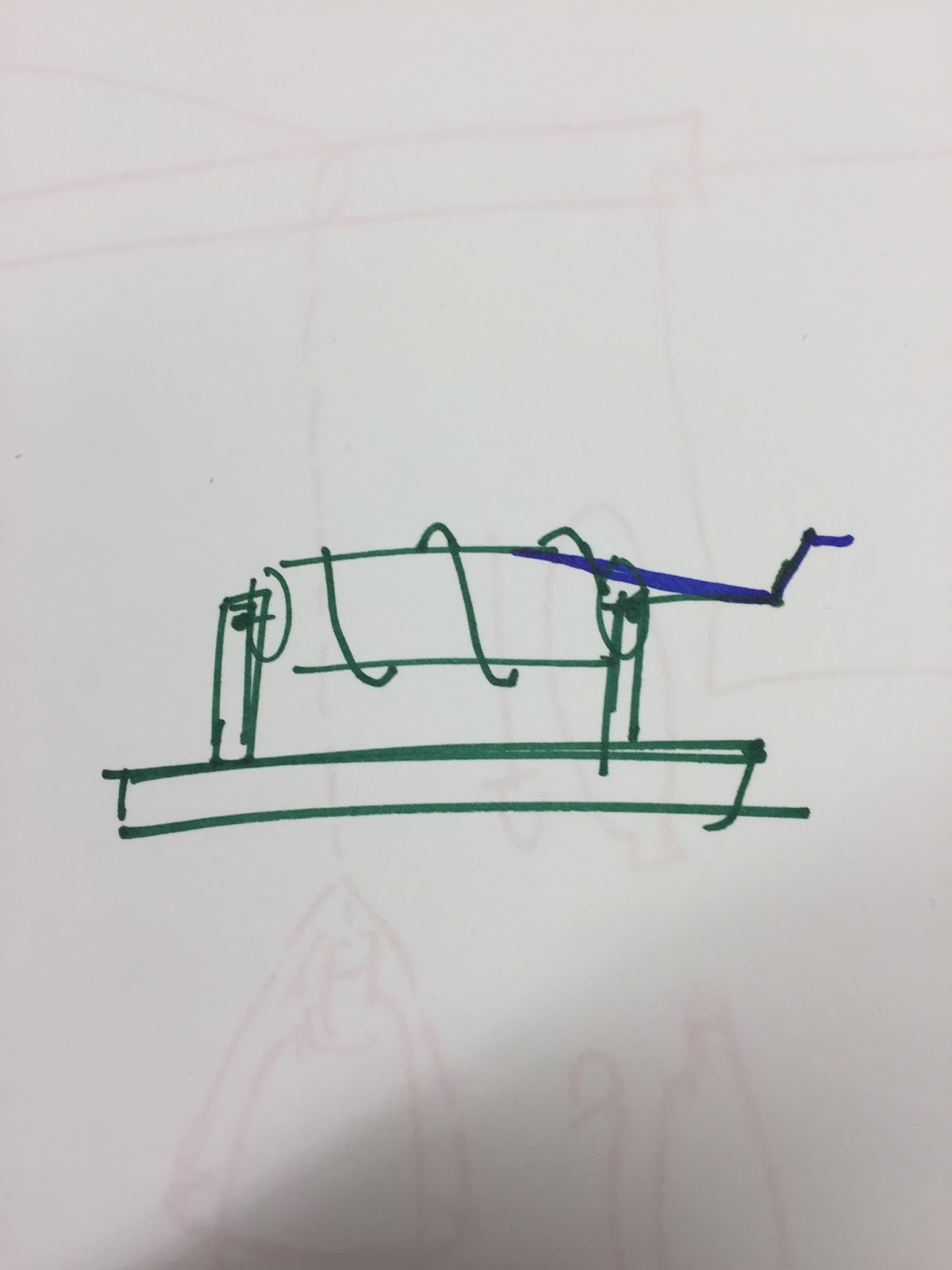
For this project, Rachel and I began by brainstorming ideas for the windlass. We made sketches of the whole windlass:


and for specific parts of the windlass with more detailed and specific designs:


Rachel and I then discussed which designs we liked best and began incorporating our ideas in to a small scale prototype made out of cardboard. We originally wanted to use triangular supports and make a sort of pyramid. Triangles are very strong structures, whereas squares are not. We would connect the supports using Delrin rod, which would also be used to pull up the string some how. The challenge with this, however, was that we would have to cut out holes at an angle in order to fit the Delrin rod at the top like we had hoped. We also ran in to a lot of trouble when it came to how to attach the crank and the mechanism that would wind up the string. We knew we had to make some changes, so we wanted to build an actual size model so we could figure out the specific details.


Day 5 (2/9/16)

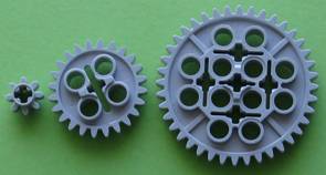
Today we started off class by talking a little bit about mechanisms. We talked about gears and gear trains, belt and chain drives, cams and followers, and linkages. See my "Mechanisms" post to learn more about gears and gear trains.

After our short introduction to mechanisms, Rachel and I went back to work on our well windlass. We made our foam core prototype and incorporated a few changes to our design. We decided to have the sides at a 90 degree angle to the table in order to make our fastening and attaching simpler. Unfortunately this gave our design a square shape, which is not the most stable. To give our structure extra support, we decided to incorporate beams on the sides. We decided that in order to make the structure stronger and more stable, we would use triangular beams at an angle that would connect the top of one structure to the bottom of the other.

We also figured out a way we could wind up the string and pull up the bucket. We decided we would cut out two Delrin disks with a hole in the middle and three holes in a circle farther out from the center. The center hole in the disk would have the main support rod that would go through both triangular structures and the other three holes would have smaller pieces of Delrin rod so that when we wound it up, the string would wind up quicker and would have more support. With just a single beam going through, there would not be enough strength to support the liter bottle of water. Here is where the physics equation for cantilevers comes in to use. We can control the length of the rods (to a certain degree) and the thickness (by adding rods together or around each other), however we cannot control Young's modulus or the applied force. In order use the changeable variables to our advantage, Rachel and I added more rods around in a circle to increase the effective thickness of the "cantilever." We also tried to minimize the length of the effective cantilever. Had we had more rod, we maybe could have added more long beams in the center for extra support of the main crank system. We could have also improved the strength by using a different material, with a larger Young's modulus, instead of the Delrin rod. Also with the increased effective radius of the wheel, we were able to increase the speed at which we could crank up the bottle. Instead of just having the string wrap around one rod, it wrapped around 3. We could have made it faster by increasing the effective radius, but we were under a materials constraint and couldn't make the disks much larger than we had them.

Rachel and I struggled a lot with figuring out how to crank the windlass. We originally had the idea that we would cut out a circle in one of the supports and instead of having both disks with the Delrin rods on the inside of the support structure, we would have one on the inside and one just outside the support structure. We planned to make one of the connecting pieces of Delrin rod longer than the other so that we could crank it around in a circle like this:


Here is what our final foam prototype looked like:


Once we finished our foam core prototype, we began designing our pieces in SolidWorks. We had to make a few changes so that we could meet the 500cm^2 limitation:


In order to attach all of our pieces, we decided to use slots and pegs, as well as cut out holes for the Delrin rod. Before we printed out any of the big pieces, we tested out our measurements in SolidWorks and the laser cutter so we could ensure the tightest, best fits possible. We cut out the pegs and slots and holes about 5 times each and finally figured out what measurements to use in SolidWorks so that the laster cutter cut them the right size. We then made sure all of our measurements were accurate and cut out all of the pieces that we needed.

We worked on cutting out the pieces and putting together our prototype all the way up to the next class period on Friday.

Day 6 (2/12/16)

Today was the day we were all supposed to test our windlasses. Rachel and I were able to finish our very first prototype and put together all of the pieces:


Unfortunately, our prototype had a lot of issues and was unable to pull up the liter of water without a lot of support and effort from us. It was warped and twisted due to the diagonal support beams (and likely incorrect measurements). It was also very imbalanced because of the asymmetrical placement of wheels. Another issue was that we ran out of Delrin rod, so we weren't able to put rod in all three slots, which also caused a lot of problems.

Thankfully, Amy decided to give us all an extension on the project so we could get our first prototype working somewhat successfully. She gave Rachel and I a few suggestions on how to fix our prototype and gave us some hints as to where we went wrong.

Rachel and I went to work the rest of the class deciding how we were going to fix our issues and what design changes we would need to make.

We decided that instead of having our support beams come diagonally across, we would just use horizontal beams towards the top of the structure to prevent warping and twisting of the material. We also decided to put both of the Delrin disks on the inside of the structure and get rid of the big circle cut out in one of the structures. This was to make the design symmetrical and more stable. We also decided that we could move the disks closer to each other so that we would have enough Delrin rod to use in all three pegs.

As for the cranking part, we decided to attach a handle to the middle rod and spin it from outside of the structure. Unfortunately, the fittings weren't tight enough to allow us to spin the center rod effectively. To fix this, we used piano wire to attach the disks to the center rod, the center rod to the crank that we made, and the crank to the extra Delrin rod that we used as a handle. That way none of the pieces would slip and we would be able to easily turn the crank. Our final product looked like this:


Day 7 (2/16/16)

Today we tested our first working prototype of our windlasses. Our improved prototype was much more effective than our previous one because we fixed the majority of our big problems. We were actually able to crank up the bottle without having to hold our structure super tightly.

To make sure we stayed on budget with our material, we used the setting in SolidWorks to determine the surface area of all of our parts. Our final breakdown of material we used is as follows:

Part Type Total Surface Area
Triangular Structure x2 ~310 cm^2
Disk x2~75 cm^2
Bottom Support Beam x2 ~50 cm^2
Side Support Beam x2 ~35 cm^2
Total~470 cm^2

If we had more time, we would refine our structure more and eliminate some of the excess surface area we had on our prototype. We could also shorten the support beams to save material there as well. With that excess material we could have designed another piece that would hold the structure down on the table so we wouldn't have to use our hand. We could also make the crank longer to get more leverage and be able to apply more torque to the system to allow it to spin faster.

Sunday, February 14, 2016

Mechanisms- Gears and Gear Trains

Day 5 (2/9/16)

Gears are fascinating mechanisms. Individually they seem so simple, but together they can do very complex tasks. There are so many different ways that gears can be arranged to work together as a gear train. But what I think is the most interesting about them is that they are used everywhere for so many different tasks.

Gears are pieces that have teeth along the outside so that when they engage with another gear the teeth can interlock and rotate without slipping. Many gears are circle shaped like the one on the right. However, gears can also take on the form of ovals, squares, triangles and other random shapes. As long as they can spin, they stay in contact with another gear(s) at all times, and they have teeth that wont slip when they come in contact with other gears they will be functional and useful. Gear trains are arrangements of different gears that are used to perform a certain function.

Gear trains can be arranged in many different ways with specific names for different kinds of arrangements. While there are many different arrangements, I want to specifically talk about
planetary gear wheel trains. A planetary gear wheel train has elements and iterations of a central gear, sometimes called "the sun," an outer ring gear, and central intermediate gear(s), often called "planets." Out of the three different types of pieces, one of them must be fixed. For example, the planetary gear wheel train on the left has its center "sun" fixed in the middle and the outer ring fixed. The intermediate "planet" gear gets spun around the sun in the middle and rides along the outer ring. Planetary gear wheel trains can be much more complicated than this model too.

Gear trains, especially planetary gear wheel trains have a variety of uses. They are used in the transmissions of modern cars as well as for speed reduction in robotics and control actuated machines. They are also used in electric screw drivers and bulldozer power trains (http://machinedesign.com/motion-control/world-planetary-gears).

Gears are useful and timeless mechanisms that I believe will always have an impact on society and technology. With so many uses and a arrangements, they can be used in almost an infinite amount of situations and accomplish almost an infinite amount of tasks.

Sunday, February 7, 2016

Fastening and Attaching

Day 3 (2/2/16)

Today we learned three different methods of fastening and attaching: heat staking, fastening with piano wire, and attaching using slots and pegs. Each of these ways of fastening and attaching were taught at individual stations where we also learned how to use new tools and equipment. For this activity, I went around to the stations with my partner from the bottle opener project, Vivian.

Heat Staking:
The first station we went to was heat staking where we learned how to use the thermal press:


Heat staking is a way of permanently joining pieces of Delrin together. It is done by melting a tab of Delrin onto another piece that has a slit for the tab. It looks like this once the Delrin has been melted:


This is a great way to fasten something permanently. It is a very strong connection and it cannot be un-done. If you foresee that you will need to make changes or adjustments to your project, this is not the best way to fasten something. If you need a strong, permanent connection, this is one of the best methods.

Bushings, Pegs, Slots and Calipers:
The second station Vivian and I went to was the bushings, pegs, slots and calipers station. We first learned how to use the calipers, and then we were tasked with measuring all the dimensions of the bushings, slots and pegs.

By measuring the different pegs, slots and bushings we got an array of different measurements. For the bushings (station 1) we got measurements of 6.36mm, 6.63mm, and 6.42mm. For the peg (station 3) we measured a height of 6.89mm, a base of 4.92mm, and a width of 4.98mm. For the large slit we measured a height of 9.98mm, a base of 5.01mm, and a width of 4.94mm. For the small slit, we measured a height of 7.07mm, a base of 5.02mm, and a width of 4.98mm. For the other slits (station 2) we got a measurement of 3.23 for the thickness. For the heights, we measured a range of values of .5075 in, .5085in, and .5085in. For the bases we measured values of .14in, .1325in, and .1155in with actual values of .135in, .125in and .115in respectively. The difference in our measured values and the values in SolidWorks is likely due to the slight inaccuracies of the laser cutter. When you cut with a laster, the laser is hot enough to melt the plastic around the cut and make the cut bigger than the original design. Also, when using a laser cutter, the intensity of the laser decreases the deeper it is in to the material which causes angled cuts and a slight variation in measurements. Because of these discrepancies in measurements, its a good idea to slightly change the measurements in SolidWorks to account for the variation in cutting. Also, it is a good idea to test smaller pieces with sizes you need to make sure that the pieces will actually fit together. This way you can adjust the sizing in SolidWorks so that when you go to print the actual pieces of your project they fit perfectly.

Bushings, pegs and slots are a good way to fasten things if you do not need a permanent attachment. If you get the sizing just right however, you can create a secure, tight attachment that will work well for many things while still having the option of undoing the connection if you need to. Tight bushings are good for strong fits that restrict motion of parts. They function as if the parts were glued together without actually physically joining them. They will often work permanently, but can be undone if necessary. Loose bushings are great if you want to allow motion of parts while still connecting the pieces. For example, if you wanted to be able to slide the bushing on and off, you would use a loose one.

Drill Press, Arbor Press, Piano Wire:
At the final station Vivian and I visited, we learned how to use the drill press, the arbor press and how to fasten pieces using the piano wire and the two presses. The drill press is a machine used to drill holes in to your material. Here is my partner, Vivian, drilling a hole in some Delrin to create a hinge:

By changing the size of the drill bit you use, you can change the size of the hole to adjust for your specifications. The arbor press is used to apply a strong force to an object. For example, if I needed to put some piano wire through a hole I just drilled, and there is a very tight fit between the wire and the piece, I could use the arbor press to push the wire through the hole. Piano wire can be used for a lot of things. It can be used to just attach pieces loosely together. It can also be used to create hinges that can move freely. It is not a permanent fastening device or the strongest, but it is versatile. 

Saturday, February 6, 2016

Bottle Opener

Day 1 (1/26/16)

Today was the first day of Engineering 160. For the majority of class, our professor taught us the fundamental ideas and principles of engineering. We discussed how to systematically come up with a solution to a problem by 1. defining the problem 2. developing concepts (brainstorming ideas) 3. designing the system 4. designing the specific details of your product and 5. testing and refining your product. We also discussed useful tools to help design your product such as brainstorming, analysis, prototyping, and experimentation. We spent a lot of time talking about effective ways to brainstorm ideas and then did a few brainstorming exercises.

Towards the end of class we started working on our bottle opener project. My project partner Vivian and I spent a few minutes brainstorming ideas for a bottle opener. Below are some pictures of the designs we came up with:


After coming up with these different ideas for bottle openers, we reviewed our designs, and decided to try making "The Egg." We drew out some new iterations of the bottle opener to come up with the best possible design. Here are a few of the adjustments we talked about:


Once we decided what design we were going to use, we created a prototypes out of cardboard and foam. These prototypes were used to make adjustments for sizing and shape.


Day 2 (1/29/16)

Today in class we discussed laser cutting and important safety procedures to keep in mind while cutting. After the brief lesson, we had time to start designing our products in SolidWorks. Vivian and I had several struggles with SolidWorks that required lots of time and help to solve. Luckily for us, we had many resources (Amy, Larry, Xi Xi) that were willing to help us and we eventually solved the problems. At the very end of class, once we finished our design, we were able to laser cut our first prototype:


Unfortunately, there were several major things wrong with it. First off, the part that connected the large circle to the small circle was too narrow. The bottle was not able to fit through it without brute force. Once we were able to get the bottle through, the opener was not successful. Several factors led to the lack of success of this bottle opener. First, because of its large width (the base in the cantilever equation) and thin thickness, this cantilever was not very strong. It would bend quite a bit when we tried to open the bottle. Second, we were not getting enough torque to open the bottle when we lifted the opener. I think this was because of our design, which made it seem like we had to change our design completely.

Day 3 (2/2/16)

Today we learned different ways to fasten objects, specifically Delrin (the material we used for the bottle openers) objects. To see more details about that, visit my "Fastening and Attaching" blog. With the extra time we had between stations, we had more time to work on our bottle openers. During this time, Vivian and I completely changed our design and started again from the beginning. We eventually came up with this new design:


We planned to make it look like a key and designed it to have a little tab on the inside of the cut-out that would catch the bottom and inside of the bottle cap. Once again, we made cardboard and foam prototypes to refine our design as much as we could:


Outside of class, we designed the product in SolidWorks:


For our final design we also included an engraving of "ENGR 160" along the ring part of the key. Once we added the engraving, we were able to laser cut our new bottle opener:


The new bottle opener, the "Engineering Key to Success," had a design that would improve the functionality of the product. Because of its thicker material and shorter width, it could withstand more force and it would have less deflection when applying the necessary force to open the bottle. Also because of its design with the tab and the ring, we were able to apply a larger torque to the bottle cap which helped us open the bottle.

Directly after laser cutting, the product was still not able to open a bottle. Unfortunately, the tab was too thick to fit underneath the bottle top, so we had to file it down:


Once we filed the tab down enough so that it could fit under the bottle, the bottle opener was successful. 

Day 4 (2/5/16)

Today was the moment of truth. At the start of class we had to present our bottle openers to the class. We explained our thought process, designs, the physics behind the bottle opener, and then tested the opener on a bottle of soda. Our "Engineering Key to Success" was a success and was able to open the bottle without problems. If we were given more time to make the bottle opener, we would change the design of the tab to make it fit under more of the bottle top and make it more efficient. We would try different shapes and sizes of the tab and maybe change the shape of the cut out as well. 

Overall, this project was very successful. Not only were Vivian and I able to create a bottle opener that worked, we also learned how to design parts in SolidWorks, how to laser cut, and we learned the basic engineering principles to create a successful product. It was a great way to begin engineering and start developing our creativity and skills.